Congratulations you have just purchased what we hope to be one of the single most strength
improvement accessories for your differential.
Note: This procedure is designed to be done after the gear set has been at least partially installed such
that the Gear pattern is correct. In this way you are not guessing where to set the unit.
While you are waiting for your Install kit to arrive get your carrier or Locker off to your favorite
Machinist for modification. Tape off all holes & plug side gear holes to prevent any metal
shavings from getting inside. It would also be real handy at this point to also have an old open
carrier you could modify a bit with a grinder for doing the install as it is lighter & easier to work
with, but not totally necessary. If you do not have a machinist the following operation can be
done with a grinder as it is just for clearance, but it will be tedious.
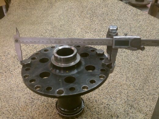
Have your carrier machined as follows, reduce flange OD to: X +.000 - .020"
[[NEED LABEL]]
D44, JK44,D50
7.305"
D70
8.800"
D80
8.925"
GM 14B
TOY 9.5
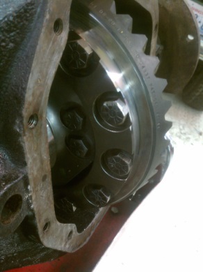
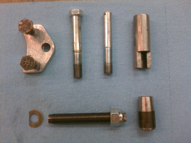
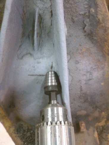
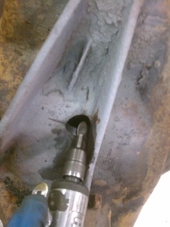
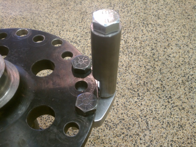
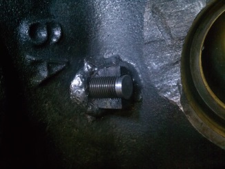
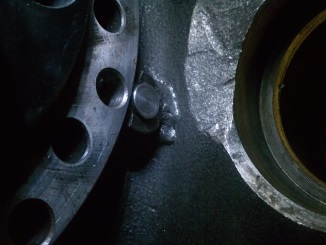
The dimension is from outside flat to outside flat of the ring gear bolts. Note that in the first
picture the bolt heads have been ground to match the curvature of the carrier flange. This
machining exposes as much of the back side of the ring gear as possible for the load bolt to ride
on. Most carriers are made of cast or nodular iron and machine rather easy, It should take less
than 1/2 hr to do it. Some carriers such as ARBs are in halves so make sure you have at least 3
evenly spaced bolts holding them together. Some carriers like this Detroit Tru track were case
hardened and it took over an hour to widdle it down to size. Note: if your machinist does not
have a micrometer that can get around the carrier and measure correctly it is possible to just
install a couple of used ring gear bolts in the holes and rotate them so the flats are tangent to
the circumference, then tell your machinist to just turn down the carrier until he tickles the
middle of the flats with his bit. Make sure you wrap these bolts with some tape to build up the
diameter of the bolt in order to center it in the hole as ring gear bolt holes will vary from a few
thousands over sized to over a 1/16" oversized.
Note: JK gears can come with either 7/16" or 1/2" bolts, the machining is based on the 7/16"
bolts, so if you are using the 1/2" bolts a little more grinding off the side of the bolt head will be
necessary.
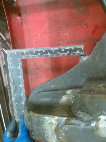
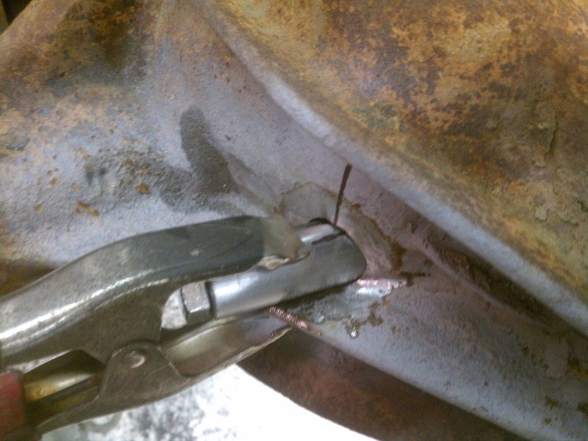
Now it is layout time. The load bolt installs on the pinion center line just under the gusset
running from the pinion center line to the axle tube center line. You will need to scribe two
lines, and where they cross is where the load bolt goes. This Video shows how.
Dimensions are as follows:
D44 housing
6 &1/16 down from the pinion housing end
D60 housings
6.5" down from the pinion housing end
D70s housings
6.875 (6 & 7/8")
D80s housings
(I don't have the actual measurement yet, please see how to find it at the end
of these instructions.
I got lucky and one of my squares just happened to be 6.5" long on the short side. Otherwise
you can use a straight edge along with a combination square to layout the line. Using light
colored spray paint I was able to scribe the line down from the pinion end. Scribe the line as
long as possible you will need it for reference later. (more than is in this picture)
Now you are ready to figure out what you are going to do with all those parts that came in the
kit. Starting in the upper left and going clock wise you have the Load bolt Indexing plate, 9/16"
installation bolt, guide pin, threaded bushing, tapered bushing, load bolt & jamb nut, &
clearance washer.
DON'T FORGET THE CLEARANCE WASHER.
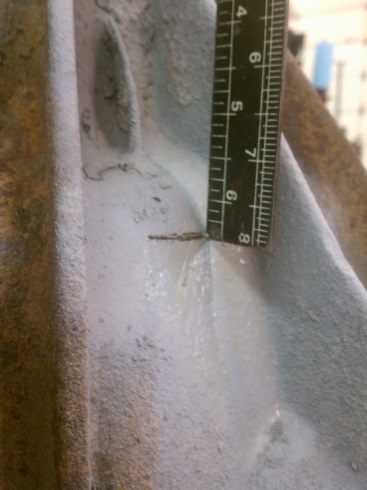
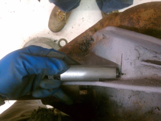
Use the 9/16" installation bolt (with the sharpened point to scribe the vertical location line.
Note" the housing rib is on and angle and you will have to grind into it a bit (see later pics as
well). Starting tangent to the outboard end of the rib and getting deeper as you go inboard so
use the clearance notch on the threaded bushing as shown to place scribe line. Again make this
line longer than shown as you will need it for reference later.
Make a good punch mark for starting your hole at the cross. Don't use the sharp point on the
installation bolt, as it is not hardened, it is just a guide. You now have a rough location to start
the drilling process, be as accurate as you can but it's ok if you are off a little as the index plate
will correct your errors as you proceed.
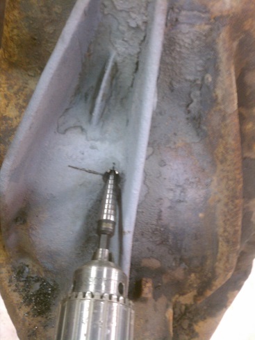
I purchased a couple of step drills from home depot. Make sure the drills you use are of the
single flute design as they are less likely to crawl sideways than the 2 flute design. The first drill
was from 1/8" to 1/2", drill it in all the way. I had to chuck it on the end of the hex so that the drill
chuck missed the rib to be able to penetrate all the way through the housing.
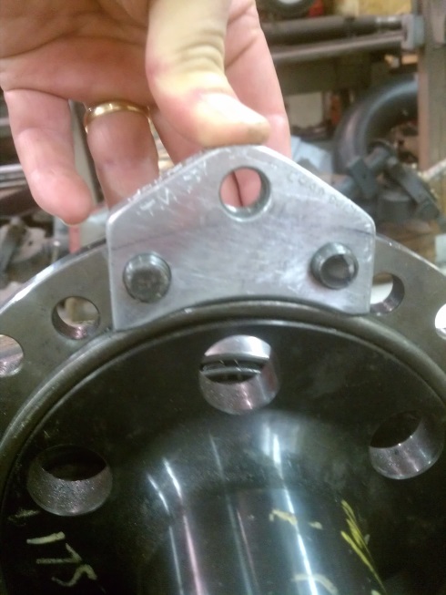
Now you will put the index tool on your carrier and look thru the hole you just drilled and
compare it for line up on the index hole. If they are inline then proceed on to next step if they
are not you will need to take your die grinder and work the hole concentric with the index hole.
The index plate is located not by the bolts but by the ring gear shoulder on the carrier. Make
sure index plate makes good contact with shoulder as bolts are tightened down. Do not use
hammer, its aluminum, you will mess it up. (note pictured is a 60 carrier with adapter ring to
make it a 70 carrier.) Note: you probably will not be able to rotate the carrier all the way around
with the index plate bolted to it, so install carrier assembly with index plate inboard. When the
carrier & index plate are fully installed you should be able to rotate the unit a few degrees each
way. IF it binds, clearance accordingly. Some of the 2nd run of index plates is not triangular as
shown, feel free to saw as shown if you need more clearance.
If you are doing Dana 80 you will need to shim out the index plate an extra 1/16", and a curved
shim is in the kit, along with special reduced shank plate bolts to allow the 1/16" offset.
Remove carrier prior to drilling, (I forgot and gouged up the edge of the carrier).
Using a no larger than 7/8" OD step drill, drill into 1/2" pilot hole. When the step drill starts
drilling into the web now is the time to get out the die grinder and clearance the web, so that
you can drill all the way through without crawling the bit sideways. This is where you need the
long layout lines (still not shown very well) for a reference so you can see if your bit is crawling
off center and correct with the die grinder:
Continue die grinding and drilling until you get the 7/8" bit thru, If is a bit crooked that's okay as you will open the hole up
to 1"+ , and since the threaded busing gets bolted to the guide plate prior to welding is has to
line up properly eventually.
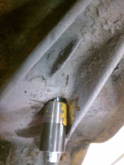
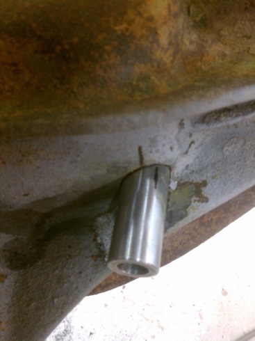
Now comes the fun part put your carrier & index plate back in the housing, and screw in the
guide pin (headless bolt with slot) and slide on the threaded bushing to see where to grind. Use
the cross hairs, (lay out lines) as a guide for staying concentric with the hole.
First I worked my way in along the housing rib, removing the guide pin and bushing, grinding a
little and then do again, I found that if I used a sharpie marker on the housing, and then
wrapped the threaded bushing with sand paper I could use it to mark right where I needed to
grind. Shiny spots within the dark area are high spots and need to be ground down.
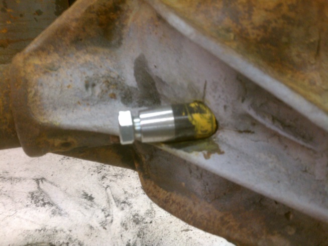
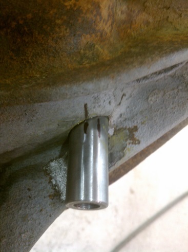
Once I could get the threaded bushing all the way to the housing staying centered on the cross
hairs I ground into the housing quite a bit and then switched to the tapered bushing.
With some gear marking compound on the tapered bushing I could see exactly where to grind,
after the tapered end when in all the way and hit the carrier I turned it around and used the
radiused end in the same fashion to complete the grinding. You have to thread the guide pin
and out many times to complete the process.
Note: I found that by shining a bright light inside
the housing out though the hole with the tapered bushing in it on the guide pin I was able to
quickly see where to do a lot of the grinding.
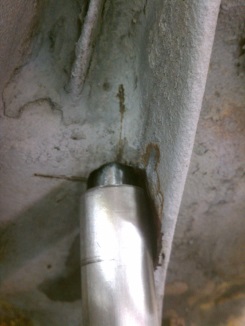
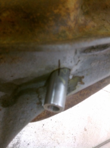
Once you can get the tapered bushing in all the way verify with the threaded bushing that it fits
as well, grind and fit a bit more if necessary. You want to be able to rotate and slide the
threaded busing in and out without touching anything. Of course you will not be able to rotate
the bushing around 360 degrees as the clearance notch will prevent this.
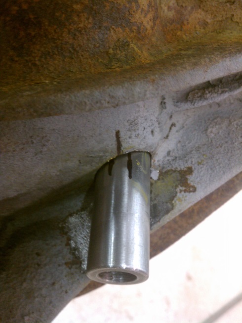
Proper location for the threaded bushing; put in hole on pin and rotate as far one way as you
can rotate it, and then make a reference mark.
Then rotate it as far as possible the other way and make another mark on just the bushing.
Then rotate the bushing and split the difference, this is the proper clocking so that the carrier
flange & ring gear bolts will clear the notch in the bushing. Extend this mark (not shown) so that
when you grind the surrounding edges for welding you do not lose the mark.
Remove carrier and grind/ prep the inside of the housing around the hole for welding, this is
easy to forget and if you manage to weld the bushing In first it is nearly impossible to do a
proper grind/prep on the inside with the bushing in the way.
Then reinstall carrier with index plate. Note: if the carrier slips in and out real easy you may
want to preload it a bit more and when you put it in this time put the carrier cap on as well to
hold it in its precise location.
This is the step where you DON'T WANT TO FORGET THE CLEARANCE WASHER. Place the
threaded bushing onto the installation bolt, and then put the clearance washer on the bolt lining
it up with the notch. Install assembly through hole and tighten installation bolt firmly. If you do
not install the clearance washer in the proper location your ring gear will be rubbing the
threaded bushing all the time. The washer goes between the threaded bushing and the index
plate not under the head of the installation bolt. (housing not shown for clarity).
When you tighten up the bolt be sure you line up your index marks on the housing to maintain
proper notch clearance to the carrier as the bushing will want to rotate as you tighten the bolt.
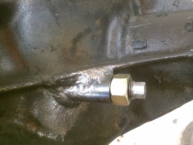
Preheat area to be welded to around 400 deg F. IF you do not have an infrared temp gauge spit
or dribble some water on the housing, if it instantly boils away you are hot enough.
Place several good tack welds around bushing.
Remove Installation bolt and carrier. If you do not remove installation bolt it will become stuck
inside bushing after welding as it will shrink up .005" to .010". Note: You will want to clean the
threads with a good tap after the weld cools down. Tap size is 5/8"-18.
Verify casting is still hot enough, re-warm if necessary. At his point there are a lot of ways
people will tell you to weld cast iron, I will just say that the nodular Iron used in most diffs welds
very nicely with a wire feed welder and a 90-10 (preferred) or a 75-25 gas mix. But prep work is
crucial, make sure all scale and rust have been removed, and nothing but shiny bare metal is
there to weld. And then grind just a bit deeper on all surfaces to remove any sand particles that
may have imbedded themselves just below the surface.
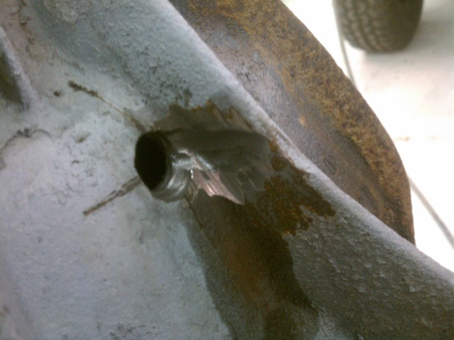
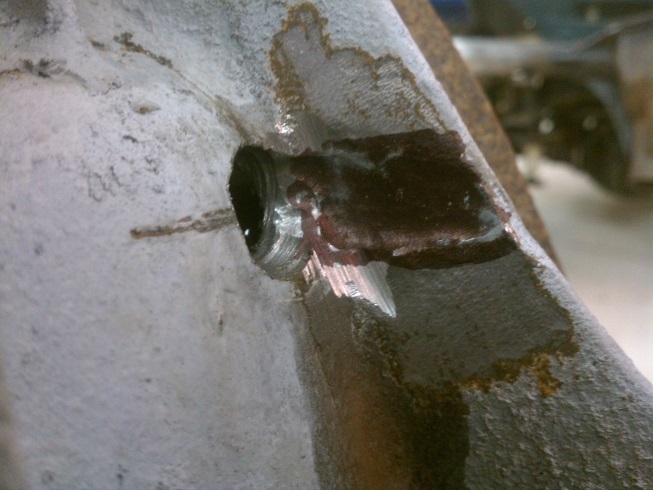
Weld no more than about 3/4 and inch at a time, and then use a slag hammer to peen the weld
immediately. If you can't peen the weld while it is still glowing you are not moving fast enough.
Weld using the back stitch method and overlap your starts & finishes. After you have finished
welding the outside, weld the inside as best as possible, (you did remember to prep the inside as
well) and try not to melt into the threads as any weldment mixed with cast Iron is harder than
the hubs of hell and will destroy your tap on clean up. If there is any weld in the thread use
carbide Dremmel tool to remove it before chasing with the tap.
Before reinstalling the ring gear make sure the back side is free from any nicks, run a file on the
back side and feel for any high spots. Sand smooth. Polish ring gear, this can be done on a
buffer, with polishing compound or use a fine grit scotch brite wheel.
35. Verify ring gear run out. Note prior to adjusting load bolt run a dial indicator on back side of ring
gear, there is always a slight bit of run out. Mark the high spot as this is where you will want to
set the clearance. If you have more than .002" run out you should get it fixed before proceeding.
Sometimes just pulling the ring gear off and reinstalling it 180 degrees can correct a slight bit of
run out.
The load bolt clearance is .003" To set, place a bit of oil on the back side of the ring gear, turn in
the load bolt till you can just barely feel it touch ring gear. If you cannot easily turn it with your
fingers all the way, check for debris in the threads, re-tap, clean and check for any nicks on the
load bolt and remove with a small triangular file. IF you can't run it in with your fingers you will
not be able to feel it hit the ring gear. Then rotate it back One Eighteenth of a turn. This is
calculated to give you .003" clearance. Now judging an 1/18 of a turn may at first seem a little
difficult, so follow along this procedure. After the load bolt just touches the ring gear scribe a
line on the head of the bolt, to do this use a straight edge, 12" scale etc, and place it somewhere
on the housing such that you can remove it and replace it in the exact same location, make small
scribe mark if necessary. Then picture in your mind rotating the bolt half way (but don't actually
rotate it) that would be a 1/2 turn, then imagine a 1/4 turn, cut that in half and you have an 8th turn
and finally cut that in half and you have a 1/16 of a turn. Now a 1/16 of a turn calculates out to
be .0035" just a half a thousandths more than you want and realistically close enough.
So now rotate the load bolt just slightly under a 1/16 of a turn (1/18 of a turn) and placing the
straight edge back in the exact location as before scribe another line. Put some thread sealant
on the 5/8" nylock nut and tighten it, keeping the second scribe mark in line with the straight
edge.
You are now done, but just to be sure, rotate the pinion by and verify there is nothing rubbing in
the assembly.
Have Fun and hammer down.
DANA 80
Determining dimensions, sorry I don't have a D80 housing to verify this, but if you assemble the index
plate on the carrier and then put the guide pin bolt on the pinion side of the unit.
You can then measure down from the end of the pinion snout to the edge of the guide pin. Take that
dimension and add half the bolt diameter (.282") (1/4" plus) to it and this will be your starting dimension
down from the pinion housing end. Make sure the guide pin bolt is centered in the pinion bore prior to
measuring as rotating it a bit will change the dimension. I wedged the carrier so it would not rotate then
used a measuring tape and a straight edge to find the measurement.
rev: b, date: 10/10/2012
Copyright Jantz Engineering, All rights reserved.
20555 Pugh Road NE - Poulsbo, WA 98370
(360) 598-2773
Copyright (c) Jantz Engineering, All rights reserved.